Rabu, 10 Mei 2006

S/PDIF - TOSLINK interface

Circuit & Information on TOSLINK interface


So you want to get a high quality audio for minidisc recording but when
using red and white RCA, the quality drop drastically. Here a my cheap solution for you.
Actually you can find a lot of references of this type of simple project in the internet.


REF


* S/PDIF = Sony/Philips Digital Interface

* TOSLINK = (

TOSLINK Interconnect History & Basics

)

* Another web offering the same information


* SPDIF at epanorama.net


Meet my version of cheap, 2 components TOSLINK @ S/PDIF.
Try to find a cable with connector from old PC casing for this.
(HDD led,reset switch or power button connector)


Assemble it using your own creativity. Use the pen tube for the light transmission.


Connect it to the back of your CDROM drive. Since (D, the signal should go to anode and G should go to the ground/cathode)


Test it out. you should see the light come out from the tip/tube.


Connect to your MD or other device such as power amp that support optical in.


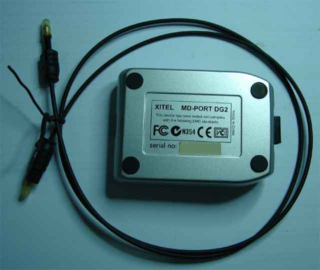
Actually, I have one of this (USB to SPDIF converter) for my minidisc but just to share with you on how to find a supercheap
solution before start buying. :-)


Even my new MSI mainboard do have built-in TOSLINK :-)

Jumat, 05 Mei 2006

PC IrDA interface

DIY IR interface


This circuit is also from www.electronics-lab.com.
Since it is very hard for me to get the infrared interface (TFDU4100), I start to look in the old/damage handphones.
It looks something like this.


Now, you need to remove it using the hot air blower perhaps.


Connecting to motherboard


Please refer to www.electronics-lab.com
on how connect this irda module to your motherboard.

My IrDA


Infrared Transceiver Modules


Here are the pin layout and picture of the device.


Pin Description of TFDU4100


Pin Number Function Description I/O Active
1 IRED Anode
IRED anode, should be externally connected
to VCC2 through a current control
resistor
2 IRED Cathode
IRED cathode, internally connected to
driver transistor
3 Txd Transmit Data Input 1 High
4 Rxd
Received Data Output, open collector.
No external pull–up or pull–down resistor
is required (20 k. resistor internal to device).
Pin is inactive during transmission.
0 Low
5 NC Do not connect
6 VCC1/SD Supply Voltage / Shutdown
7 SC Sensitivity control 1 High
8 GND Ground

Rabu, 26 April 2006

Touch Switch


Experiment With NAND Gate - CMOS 4011


Output goes high when touch wires bridge by finger.

Gates Oscillator

Experiment With NAND Gate - CMOS 4011


(CMOS 4011 Layout)


Circuit


Try this super-simple experiment. The output frequency is about 1kHz (square wave).

Rabu, 19 April 2006

Telephone FM Transmitter


Descrition & Circuit


This project is taken from www.electronics-lab.com.

With some modification, I create my own version of FM Telephone bug complete with stripboard layout.

Theortically, the frequency range is from 88MHz to 94MHz but you may experiment with the coil structure to tune it


Circuit


Strip Board Layout


Parts List


Diode IN4384 4
LED 1
Resistor 12k 1
1k 1
200R 1
Capacitor 470p 1
330p 1
25p 1
12p 1
Transistor A933(PNP) 1
Coil *See note 1

*Coil note

7 or 8 turns of 22AWG(diameter .6mm) around 9/64inch(3.6mm) drill bit. Antenna using the same wire 22AWG, 5inch long


Picture


Compact!


With antenna!


Put it online!


Get ready to tune your radio!


Senin, 10 April 2006

Lab Power Supply


Description and Circuit


Make your own lab power supply complete with adjustable voltage and constant current source.

Using single IC (LM324)

Here is the circuit.


Strip Board Layout.


Part List


1 LM324 Opamp

1 Ammeter 100 µA 1k ohm

1 Voltmeter

6 IN4001

1 Zener Diode 9.1V

1 Full-Wave Bridge Rectifier

1 LED

2 NPN Transistor, 2N3055

1 NPN Transistor, BC109C

1 Transformer

2 E-Capacitor 2200µF

1 Potentiometer 5k ohm linear

1 Potentiometer 10k ohm linear

1 Resistor 500 ohm

2 Resistor 2.2k ohm

1 Resistor 560 ohm

1 Resistor 6.2k ohm

2 Resistor 68k ohm

1 Resistor 0.22 ohm

4 Resistor 4.7k ohm


Component Image.


LM324


2N3055


Some Pictures.


Twitter Delicious Facebook Digg Stumbleupon Favorites More

 
Design by Free WordPress Themes | Bloggerized by Lasantha - Premium Blogger Themes | Best Web Host